Page 6
Button 6 - This button activates Outlets 4 and 5. This button cycles in the
following manner:
1st Press - Activates Outlet 4
2nd Press - Activates Outlet 5
3rd Press - Activates Outlets 4 & 5
4th Press - Deactivates Outlets 4 & 5
Button 7 - This button activates Outlet 6.
Button 8 - This button activates Outlet 7.
Button 9 - This button activates Outlet 8.
Multi-Function Deactivation - To turn off all active operations, press and
hold any active keypad button for at least 2 seconds.
Dip Switch Functions
The amp/relay module contains a bank of 4 dip switches. The function of
each switch is as follows:
DS1 - This dip switch must remain in the ON position at all times.
DS2 - This switch determines the audio characteristics of the WAIL siren
tone. If the DS2 is in the OFF (default) position, an ‘electronic’ siren tone
will be generated. If DS2 is in the ON position, a simulated ‘mechanical’
siren tone will be generated.
DS3 - This switch controls the siren pursuit tone. If DS3 is in the ON
position, the WAIL tone is generated when button 3 is pressed. If DS3 is in
the OFF position, no siren tone is generated when button 3 is pressed.
DS4 - This switch determines the method that will be used to turn the siren
system on. If the switch is in the ON position, the system is turned on by
switching the high-current main power lines (1-3 & 1-4). If this is desired, a
switch sized to handle the entire current load must be installed in-line with
both 1-3 and 1-4.
If the DS4 is in OFF position, the system is turned on via the LCPA wire (5-
3 or 5-8).
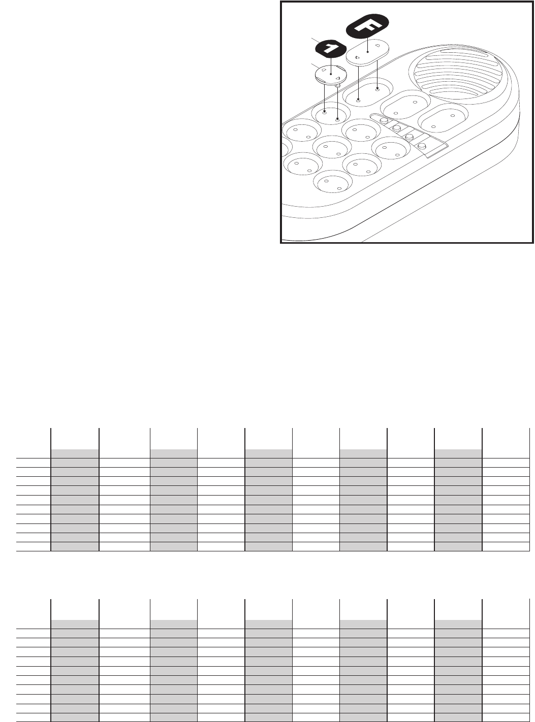
NOTE: The controller is shipped without any button decals installed.
Do not place button decals directly onto the buttons. Install a plate
onto each button first and then adhere the desired button decal onto
that plate.
Programing
The button functions of the controller may be reprogramed using the HHS
2200 Plus Configuration software. The amp/relay module must first be
connected to the programing computer via the USB Port.
Refer to the online help provided with the software for programming
procedures.
Wire Gauge Chart
5 Amps
55 Amps
10 Amps
60 Amps
15 Amps
65 Amps
20 Amps
70 Amps
25 Amps
75 Amps
30 Amps
80 Amps
35 Amps
85 Amps
40 Amps
90 Amps
45 Amps
95 Amps
50 Amps
100 Amps
6 Feet 3 Feet Insufficient Insufficient Insufficient Insufficient Insufficient Insufficient Insufficient Insufficient
22 AWG
20 AWG
18 AWG
16 AWG
14 AWG
12 AWG
10 AWG
8AWG
6AWG
4AWG
2AWG
9.5 Feet 5 Feet 3 Feet Insufficient Insufficient Insufficient Insufficient Insufficient Insufficient Insufficient
15 Feet 7.5 Feet 5 Feet 4 Feet 3 Feet Insufficient Insufficient Insufficient Insufficient Insufficient
24.5 Feet 12 Feet 8 Feet 6 Feet 5 Feet 4 Feet 3.5 Feet 3 Feet Insufficient Insufficient
39 Feet 19.5 Feet 13 Feet 9.5 Feet 8 Feet 6.5 Feet 5.5 Feet 5 Feet 4.5 Feet 4 Feet
62 Feet 31 Feet 20.5 Feet 15.5 Feet 12.5 Feet 10.5 Feet 9 Feet 7.5 Feet 7 Feet 6 Feet
98 Feet 49 Feet 32.5 Feet 24.5 Feet 19.5 Feet 16.5 Feet 14 Feet 12.5 Feet 11 Feet 10 Feet
156 Feet 78 Feet 52 Feet 39 Feet 31 Feet 26 Feet 22.5 Feet 19.5 Feet 17.5 Feet 15.5 Feet
248.5 Feet 124 Feet 82.5 Feet 62 Feet 49.5 Feet 41.5 Feet 35.5 Feet 31 Feet 27.5 Feet 25 Feet
395 Feet 197.5 Feet 131 Feet 98.5 Feet 79 Feet 66 Feet 56.5 Feet 49.5 Feet 44 Feet 39.5 Feet
629 Feet 314 Feet 209 Feet 157 Feet 125.5 Feet 104.5 Feet 89.5 Feet 78.5 Feet 69.5 Feet 63 Feet
Maximum Current Draw Through The Wire
Wire Gauge
22 AWG
20 AWG
18 AWG
16 AWG
14 AWG
12 AWG
10 AWG
8AWG
6AWG
4AWG
2AWG
Maximum Current Draw Through The Wire
Wire Gauge
Wire Gauge Calculation Chart
Insufficient Insufficient Insufficient Insufficient Insufficient Insufficient Insufficient Insufficient Insufficient Insufficient
Insufficient Insufficient Insufficient Insufficient Insufficient Insufficient Insufficient Insufficient Insufficient Insufficient
Insufficient Insufficient Insufficient Insufficient Insufficient Insufficient Insufficient Insufficient Insufficient Insufficient
Insufficient Insufficient Insufficient Insufficient Insufficient Insufficient Insufficient Insufficient Insufficient Insufficient
3.5 Feet 3 Feet 3 Feet 3 Feet Insufficient Insufficient Insufficient Insufficient Insufficient Insufficient
5.5 Feet 5 Feet 5 Feet 4.5 Feet 4 Feet 4 Feet 3.5 Feet 3.5 Feet 3.5 Feet 3 Feet
9 Feet 8 Feet 7.5 Feet 7 Feet 6.5 Feet 6 Feet 6 Feet 5.5 Feet 5 Feet 5 Feet
14 Feet 13 Feet 12 Feet 11 Feet 10.5 Feet 10 Feet 9 Feet 8.5 Feet 8 Feet 8 Feet
22.5 Feet 20.5 Feet 19 Feet 17.5 Feet 16.5 Feet 15.5 Feet 14.5 Feet 14 Feet 13 Feet 12.5 Feet
36 Feet 33 Feet 30.5 Feet 28 Feet 26.5 Feet 24.5 Feet 23 Feet 22 Feet 21 Feet 19.5 Feet
57 Feet 52.5 Feet 48.5 Feet 45 Feet 42 Feet 39 Feet 37 Feet 35 Feet 33 Feet 31.5 Feet
 (3 pages)
 Manymanuals.com
 Manymanuals.de
 Manymanuals.fr
 Manymanuals.it
 Manymanuals.pl
 Manymanuals.cz
 Manymanuals.es
 Manymanuals-pt.com
Comments to this Manuals