Whelen 7101104 User Manual

Browse online or download User Manual for Air equipment Whelen 7101104. Whelen 7101104 User Manual

  • Download
  • Add to my manuals
  • Print
  • Page
    / 2
  • Table of contents
  • BOOKMARKS
  • Rated. / 5. Based on customer reviews
Page view 0
Page 1
Model:
7101104
Model: 7101104
2.17
Mounting Detail
1.750
.875
Ø1.18
2 x Ø.125
Model: 7101104
1.71
1.36
3.46
2.00
Drain Hole
(TYP 2 PLCS)
20AWG Teflon Wire
Per MIL-W-22759/43
.95 Square
Black
(Gnd)
Red
(+28VDC)
2 x 4-40 x 5/8 MS51957-18
Mounting Screws
The conditions and tests required for TSO approval of this
article are minimum performance standards. It is the
responsibility of those installing this article either on or
within a specific type or class of aircraft to determine that
the aircraft installation conditions are within the TSO
standards. TSO articles must have separate approval for
installation in aircraft. The article may be installed only if
performed under 14 CFR part 43 or the applicable
airworthiness requirements.
®
ENGINEERING COMPANY INC.
Route 145, Winthrop Road,
Chester, Connecticut 06412
Phone: (860) 526-9504
Fax: (860) 526-2009
Internet: www.whelen.com
Sales/Service e-mail: aviation@whelen.com
Aviation
Installation Guide:
Model 7101104
P/N: 01-0771011-04
LED Tail Position
Light Assembly
©2007 Whelen Engineering Company Inc.
Form No.14098A (061008)
TSO-C30c
TYPE III
APPROVED
MADE IN THE U.S.A.
OPERATING INSTRUCTIONS:
Nominal Voltage: . . . . . . . . . . . .28 VDC
Operational Voltages: . . . . . . . .24 - 30 VDC
Input Current:. . . . . . . . . . . . . . .0.3 Amps
EQUIPMENT LIMITATIONS: The approved tail position
light assembly should be mounted vertically and as far aft
on the aircraft as possible, on a thermally conductive
surface
CONTINUED AIRWORTHINESS: The LED tail position
light assembly is designed with 6 LED’s. If any one LED
fails, the unit must be repaired or replaced. Inspect the
lens. Replace if there is excessive scratching, discoloration
or cracking.
INSTALLATION PROCEDURES: The following
information is to assist you in installing a Whelen tail
position light.
1. Choose the appropriate model light assembly which
is most applicable to your aircraft.
2. Remove the old light, locate and save the existing
+28VDC lead and (-) ground lead. Clean and prep
ends as required.
3. Use the existing mounting holes and hardware.
4. Connect the existing +28 VDC lead to the red 20
AWG lead. Connect the black 20 AWG wire to
ground. Both leads must be connected by FAA
approved techniques using approved hardware.
5. Make sure the existing system is equipped with an
appropriate sized breaker.
6. Remove two #4-40 screws from tail light assembly.
Save these screws.
7. Install the light assembly and insure that all the leads
are clear of any obstructions and ty-wrap as required.
Secure light assembly using approved vibration
resistant hardware methods. Note “Top” marking on
the unit.
8. Re-mount the lens and retainer onto the assembly. Attach the
lens and retainer with mounting screws (provided).
9. Check all avionics systems for interference from this installation.
10. When waterproofing the assembly to the aircraft, apply aviation-
approved single part silicone (RTV) or equivalent around the
periphery with caution. Do not fill the drain holes at bottom of
unit. RTV should never be used between the rear surface of
the light assembly and its mounting surface.
11. Update aircraft records, complete Form 337 and obtain FAA
field approval for installation.
Model Shown:
7101104
Page view 0
1 2

Summary of Contents

Page 1 - Aviation

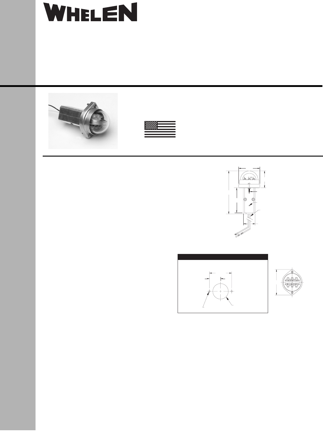
Page 1Model:7101104Model: 71011042.17Mounting Detail1.750.875Ø1.182 x Ø.125Model: 71011041.711.363.462.00Drain Hole(TYP 2 PLCS)20AWG Teflon WirePer MI

Page 2 - (2 Places)

Page 2Model: 7101104WHELEN2311ITEM PART NUMBER DESCRIPTIONMODEL 7101104 LED TAIL POSITION LIGHTLED VERTICAL MOUNT TAIL POSITION LIGHT (28V)GASKET, LEN

Comments to this Manuals

No comments